My Rachio Died, so I built my own
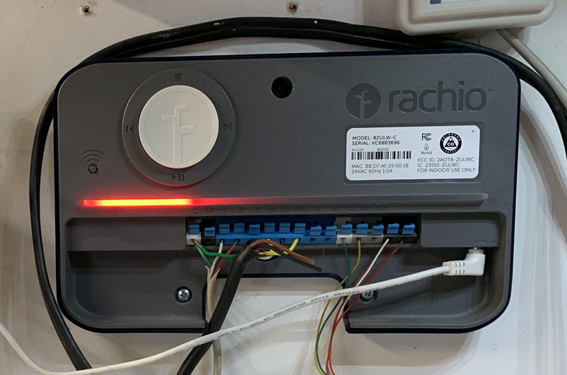
My Rachio sprinkler controller failed after only six years. I assumed it would last much longer, but customer support confirmed that the red light showing on the device’s status bar indicated a boot error and that the device was dead. I initially pursued a replacement through their support team, but after a week of back-and-forth emails and okay-ish service, I lost interest and chose to go in a different direction.
I changed course primarily because I realized I had a great opportunity to get started with ESPHome by building my own replacement controller instead. ESPHome is a software framework that can be installed on low-powered wifi microcontrollers. The supported hardware is usually very low cost and can be heavily customized. This meant I could potentially build a more fine tuned controller and integrate it better into my Home Assistant instance than I could with another Rachio, which is something I found quite appealing.
Yes, it was going to be more work than simply buying a replacement unit but the trade-off for what could be a better system (Rachio’s adaptive watering always starved my grass) and a fun learning experience with ESPHome seemed like it could be worth it. And it was, now that I am a few month past the start of this project.
Hardware
Before this project, I had never really given much thought as to what may be inside a sprinkler controller. But my reaction when
Before my Rachio died, I never thought much about what the inside of a sprinkler controller may look like. And maybe it’s the result of modern component miniaturization but I was definitely expecting to see
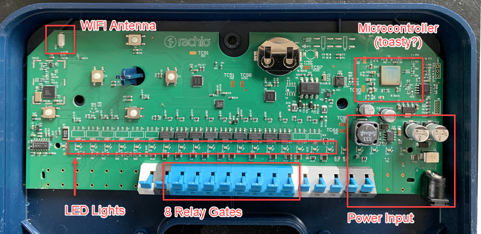
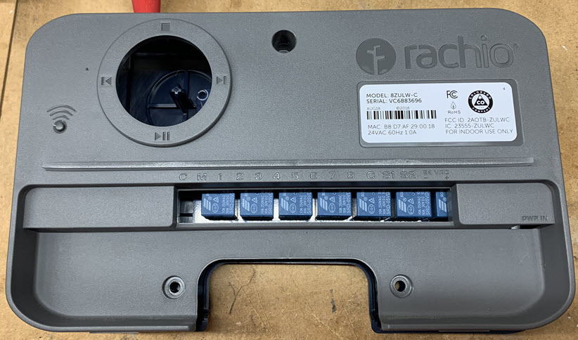
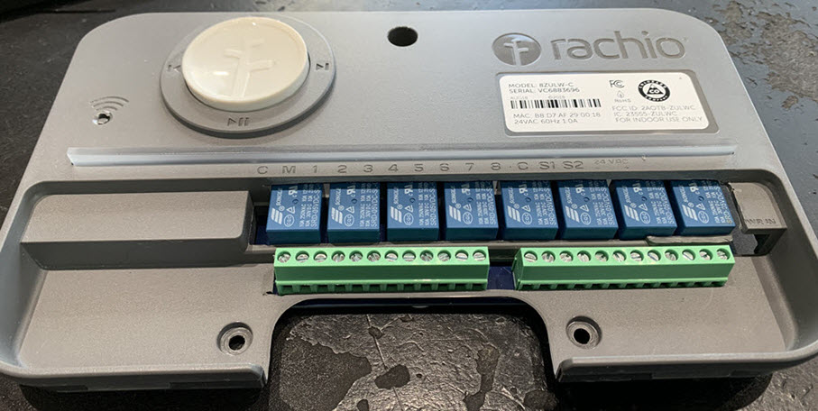
I never really appreciated the basic nature of a sprinkler controller until I had a look inside my Rachio when it died. I’m not exactly sure what I was expecting to find, but I’m pretty sure it was more “stuff” than the single PCB board that I found (below).
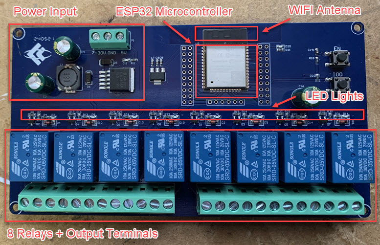
While there were many replacement board options to choose from, I wanted to keep things simple, so I opted I opted to go with this integrated ESP32 based 8 Channel Relay Module from Amazon. The manufacturer’s specs are here.
It’s not as refined as Rachio’s board, but you can see it has all the same basic components.
Another motivating consideration for my board selection was that it had a similar form factor to the old one, which meant there was a chance I might be able to reuse the old case. Here, I am doing an initial fit check to get an idea about the internal positioning of the new board and whether it could work.
Some modifications were clearly needed, but nothing I couldn’t solve with use of a Dremel and some filing. With luck, I might even be able to reuse the light bar indicator on the Rachio case since the LED Lights on both boards are in the same approximate positions.
Here’s final fit test. A little rough in a couple spots, but more than functional for my needs.
Knowing that I cold reuse the old case also served another purpose. It told me where I needed to position the board and what space was left to use for wiring and power management.
The board and the downstream sprinkler valves had differing electrical requirements so this is where some decisions needed to be made:
- The board required 5-30V direct current (DC) to operate.
- The valves required 24V alternating current (AC) to function properly.
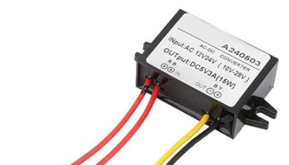
One way I saw this handled, like in this post, is to just use two separate power adapters, each providing a different voltage and current. That’s fine, but it felt like a step back from my prior setup. I wanted to find a way to power both from a single power supply. Fortunately, this is what step-down converters are designed to do. I just needed to find one that could take a 24VAC input and convert it to a 5VDC output.
Here’s the one I used. It seemed like the best candidate over alternatives that could fit neatly inside my Rachio case.
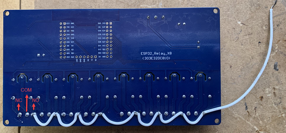
To deliver the 24VAC to the sprinkler valve solenoids, I liked the solution the poster did in this thread to soldier a jumper wire directly to the backside of all NO terminals on the relay gates. They were using 24VDC so I had to wire mine a little differently to work with 24VAC.
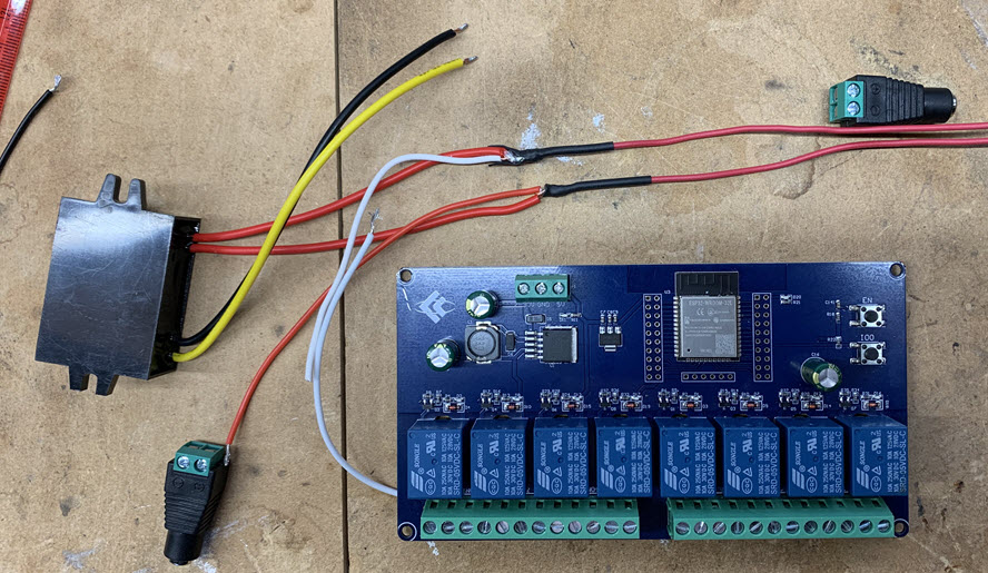
With all the main components determined, the next step was to determine how to wire everything together. The power supply delivered 24VAC and I needed to account for how that would be routed to:
- The step down converter so it can output 5VDC to the main board (black & yellow wires in images below).
- The sprinkler terminals on the board (white jumper wire).
- The common wire on the sprinkler lines -> to complete the 24v circuit when a valve is activated (this is the green wire in the 2nd image).
Here’s the wiring arranged in its preliminary form.
And here’s the wiring in its final form (minus barrel connectors):
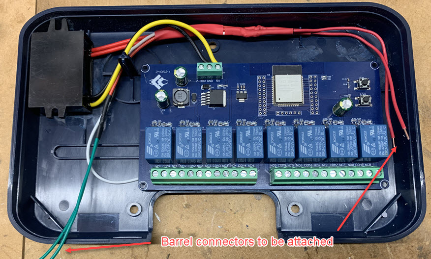
Some light filing and Dremel work was needed inside the case to make room for the step-down converter, mostly so the case lid could snap back together correctly.
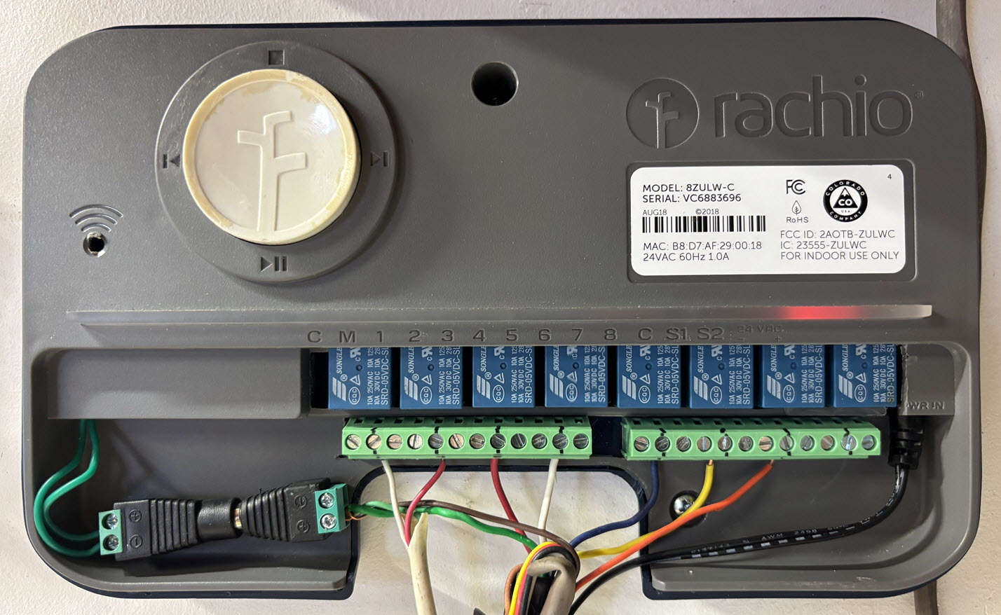
Here’s everything assembled with the unit plugged in and fully wired up. The light bar lights up decently when a zone is run, which is nice, but not that useful since the controller will always be run remotely. I think my biggest unknown going into this project is knowing how stable the wifi connection was going to be. I hadn’t used an ESP32 chip before and being in my garage the device is a little ways from my router. It’s been a few months now and I’m very happy to see that is been completely stable this whole time. Aside from the initial firmware install, I’ve always been able to perform my updates easily over wifi.
Software
ESPhome
The are several ways to install ESPHome. So if you don’t already have it installed, I’ll assume you’ll identify the right method for your situation. I run Home Assistant in a docker container, so to keep things simple, I choose to setup ESPHome the same way on the same machine.
Initial flash
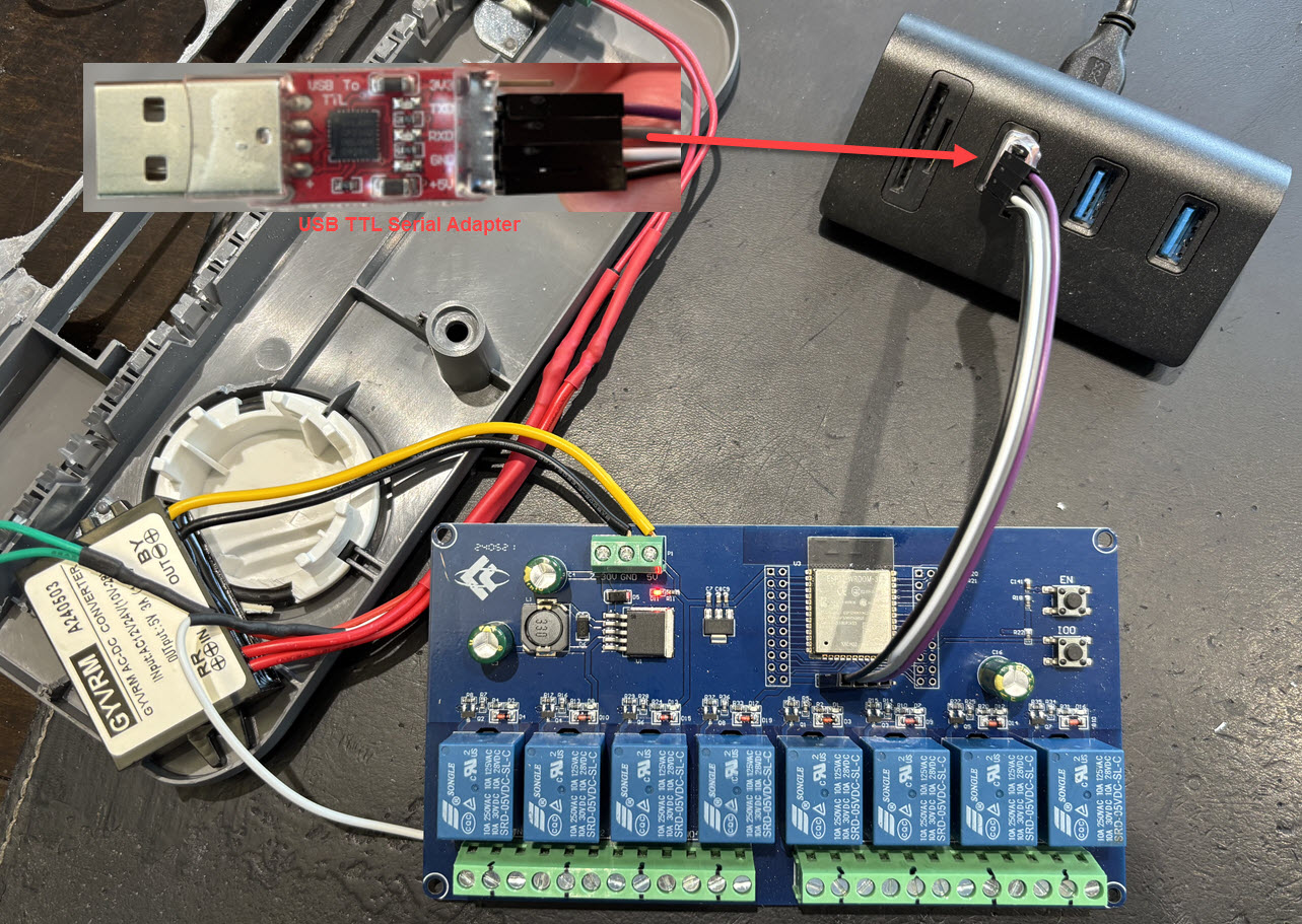
Technically, I flashed the board before doing any soldering as I would have been wasting my time if I couldn’t get the board to work.
