
Replacing my Rachio with a Custom Sprinkler Controller, Part I: Hardware
I was walking past my Rachio sprinkler controller when I noticed the status indictor bar, which normally glows blue, flashing red. At first, I didn’t think much of it, as I assumed it merely lost wifi. But when it didn’t reconnect after a few days and the usual troubleshooting steps didn’t work, I figured something else was up.
That’s when I contacted customer support, and they confirmed my device had experienced a fatal boot error. It was done. The device was only six years old and I had expected to still get several more years out of it, so the news wasn’t exactly welcomed. My first reaction was to get a replacement unit from Rachio, and I negotiated with them for about a week to that effect, but my interest in that as a solution path also quickly waned.
I had the obvious concern about the situation repeating itself in the future, but the biggest reason for my change of mind was that I realized I probably could do better if I just built my own custom controller. I loved the remote connectivity of my Rachio, but it had a tendency to water-starve my lawn and I always felt limited by the information I could view about it in my Home Assistant instance. With plenty of cheap, low-powered development boards available today, I figured it was at least worth a shot trying it myself. I had also been meaning to try out ESPHome, a software development framework for ESP-based microcontrollers, so this seemed to be the perfect setup.
Time was also on my side, as my Rachio died in February and I wouldn’t need to restart a regular watering schedule again until the middle of May. So I worked on this project in small blocks of time over a few months. In Phase I, I focused on assembling the hardware and obtaining manual valve control electronically. In Phase II, I got the zone scheduling dialed in, and in Phase III, I spent time converting my original Home Assistant scaffold UI into one that had a more finished look and feel.
Since this project involved both hardware and software elements, and for the purpose of this post, I figured breaking it into two parts would make it a little more approachable. Therefore, what follows below is Part I, with a focus on the hardware build. Part II, available here, details the software setup.
Hardware
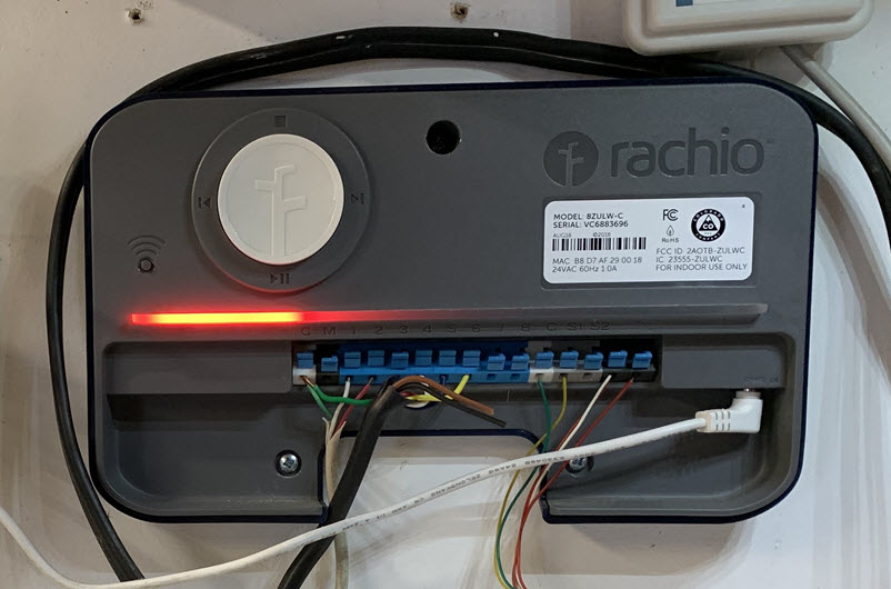
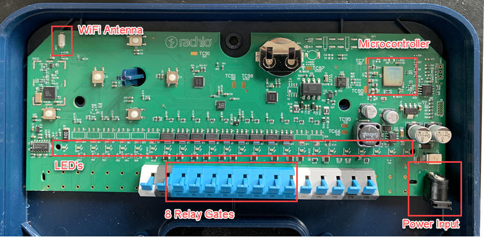
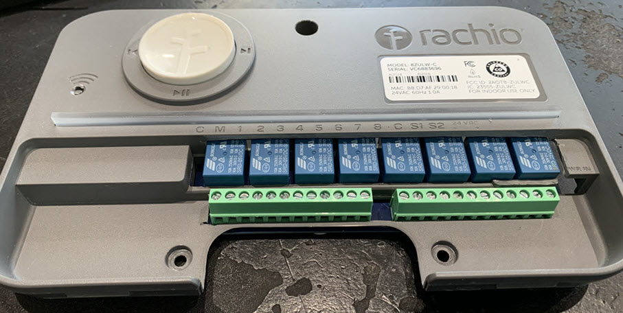
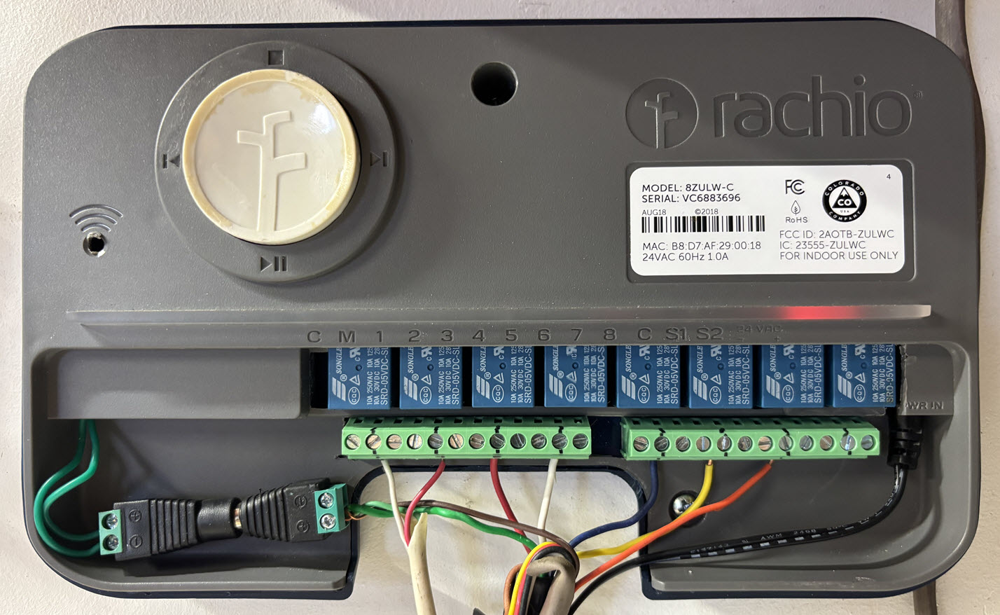
Before this project, I hadn’t given much thought to all the little bits that go into the making of a smart irrigation controller. So when I looked inside my now-defunct Rachio, I was a little surprised by what I found… or maybe I should say, what I didn’t find. The entire controller consisted of only a single circuit board. That’s it. And it wasn’t even attached to the case. I guess I was expecting to see more, but in hindsight, given how miniaturized modern electronics have become, I suppose that really shouldn’t be all that surprising.
Here’s what it looked like:
The other things that came to mind when I looked inside was the $199 retail price Rachios typically sell for when not on sale. I knew I could get a comparably equipped replacement board in the $15 to $25 range, so that implied Rachio probably acquired or produced theirs in the ballpark of $10-$15. That’s a long, long way from the sale price. Of course, they incur many other expenses to bring the product to market, but it made me wonder what their profit margin may look like.
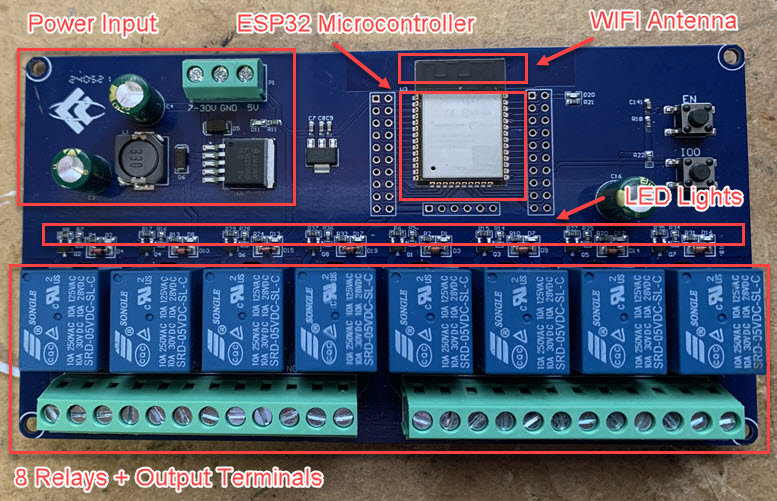
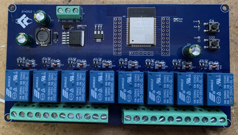
Ultimately, the board I chose to use as a replacement was this one, that I got on Amazon. I wanted to keep things simple by going with an integrated 8-Channel Relay and a similar form factor to the Rachio. The manufacturer’s specs are here.
It’s not as refined as Rachio’s board, but you can see it has all the same basic components.
The form factor was relevant because I wanted to see if I could reuse the old case. Below, is the initial fit check I did to assess whether it would work or not.
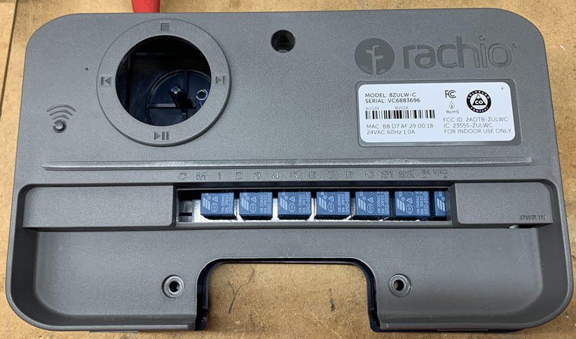
Some modifications were clearly needed, but nothing I couldn’t solve with some filing and light use of a Dremel. With some luck, I might even be able to reuse the light bar indicator on the Rachio case since the LED Lights on both boards were in the same approximate positions.
Here’s the final fit test. It’s a little rough in a couple spots, but more than functional for my needs.
Once I knew reusing the old case was a viable option, I could then move on to planning the wire routing.
The first thing I had to do was to consider how I was going to power everything:
- The board required 5-30V direct current (DC) to operate.
- The sprinkler valve solenoids required 24V alternating current (AC) to function properly.
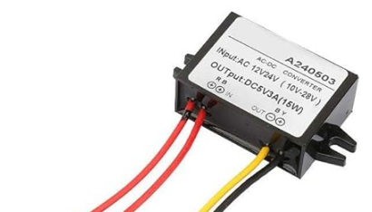
The easy way to solve this would have been to get two separate wall wart-type adapters, with each being rated for one of those two voltage requirements. But that felt like a step back from my prior setup which only used one. Step-down converters are useful in this kind of situation because they can take a certain voltage input, and as the name suggests, step it down to a different voltage output. I just needed to find one that could take a 24VAC input and convert it to a 5VDC output.
Here’s the one I used. There were many options but this one seemed like the best candidate to fit neatly inside the case I wanted to use.
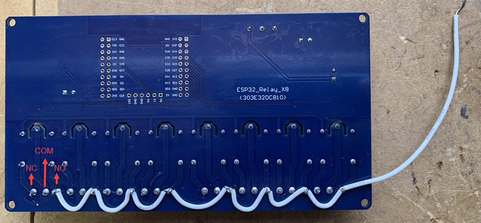
The step-down converter addressed how I was going to deliver power to the board, but I also needed to determine how I was going to get the adapter’s 24VAC to the sprinkler solenoids. I liked the method that the poster did in this post enough, that I did a modified version of it. The solution was to soldier a jumper wire directly to the backside of all the NO terminals on the relay gates. They were using 24VDC so I had to wire mine a little differently to work with 24VAC.
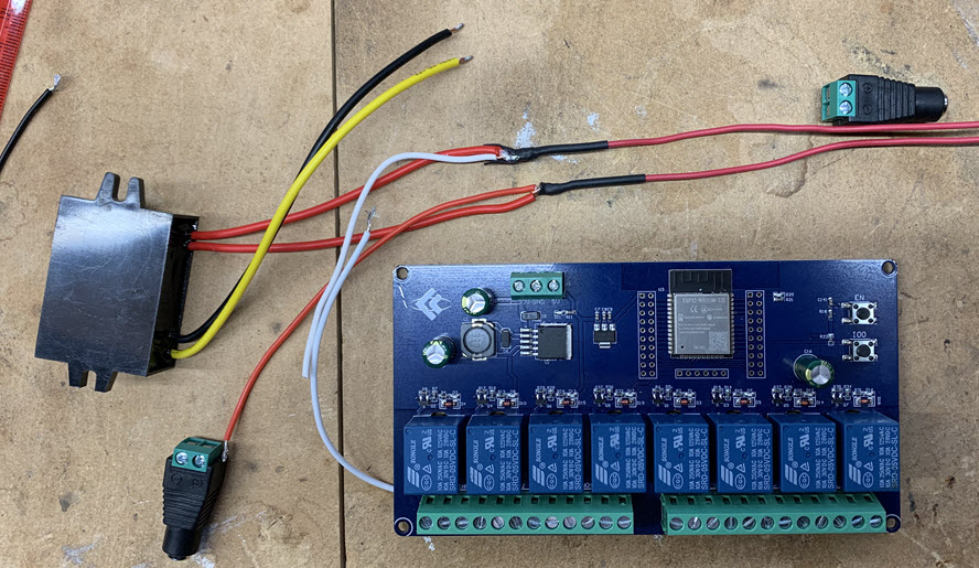
With the voltage delivery figured out, I just need to determine how to route the wiring. Here’s a quick summary of the parts in play. 24VAC from the adapter needed to be routed to:
- The step down converter so it can output 5VDC to the main board (black & yellow wires in images below).
- The sprinkler terminals on the board (white jumper wire).
- The common wire on the sprinkler lines -> to complete the 24v circuit when a valve is activated (this is the green wire in the 2nd image).
Here’s the wiring arranged in its preliminary form.
And here’s the wiring in its final form (without the barrel connectors attached):
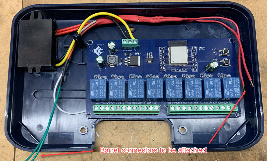
To get the case to snap back together correctly, I did have to do some filing inside the case to to make room for the step-down converter, but it wasn’t much.
Here’s everything assembled with the unit plugged in and fully wired up. The light bar even lights up decently when a zone is active, which is nice, but not that useful since the controller will always be run remotely.
It’s a little easier to see when the image above is enlarged, but the power cord from the wall adapter (black wire) attaches to the board on the right side of the relay switches. There is a barrel connector glued to the case under the grey portion of the cover.
I think my biggest unknown going into this project is knowing how stable the wifi connection was going to be. I hadn’t used an ESP32 chip before and being in my garage the device is a little ways from my router. Its now been a few months since I put this together and I’m very happy to see that it’s been completely stable this whole time. Aside from the initial firmware install, I’ve always been able to perform my updates easily over wifi.
Software
As mentioned in the introduction, the software setup is discussed in Part II to this post. That is available here.
